It’s useful to start enjoying GPIOs and also to debug some circuits without writing any line of code. It also allows to control your Pi’s GPIOs over Internet, so it’s a good starting point for home remote control.
I already wrote a tutorial about WebIOPi, but the old installation method does not work for the Raspberry Pi 3.
Install WebIOPi for the Raspberry Pi 3
Boot the Raspberry Pi 3 and make sure that it has a running internet connection. Then, enter in the terminal
sudo wget http://sourceforge.net/projects/webiopi/files/WebIOPi-0.7.1.tar.gz
I always prefer to stay updated in terms of software; I was having the version 0.7.1. may you get updated so check that out. This command download directly the file to Raspberry Pi. Now if you have downloaded the tar.gz file enter this command.
sudo tar xvzf WebIOPi-0.7.1.tar.gz
It will extract the files and put into pi’s folder name: WebIOPi-0.7.1. You can see it by entering command “ls” on the command line. Mount the folder to setup files.
cd WebIOPi-0.7.1
Now you have to write this to get the patch.
sudo wget https://raw.githubusercontent.com/doublebind/raspi/master/webiopi-pi2bplus.patch
Then install the patch.
sudo patch -p1 -i webiopi-pi2bplus.patch
Now you are in the folder, so to install the software write this
sudo ./setup.sh
Since it will download some file from internet, you need an internet connection.
Now reboot the Pi.
Set up the service
Start WebIOPi by running the command:
sudo /etc/init.d/webiopi start
If you want WebIOPi to start automatically on boot, run:
sudo update-rc.d webiopi defaults
Once WebIOPi is up and running, you can point your browser to http://yourraspberryIP:8000 (replace yourraspberryIP with the actual IP address or domain name of your Raspberry Pi) and log in using the webiopi username and the raspberry password. If everything works properly, you should see a web page with links to different sections. Click on the GPIO Header link to switch to a simple web app for controlling the GPIO pins
At the end you should see this:
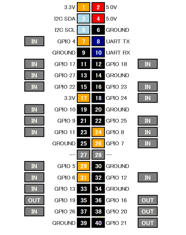
You can click on “in/out”: it will control the direction of GPIO for inputting or outputting any device or if you click on number showing boxs it will control the GPIOs in terms of “HIGH/LOW”. Yellow for high (5v) and black for low (0v).